Scheme of work of KSU
Scheme of operation of a gas piston plant
Gas reciprocating power plant (or gas reciprocating plant, mini CHPP) is a source of thermal and electrical energy based on a reciprocating internal combustion engine (ICE) that runs on natural or other combustible gas (biogas, associated petroleum gas, landfill gas and other types of gases) and hydrogen.
The scheme of operation of the gas piston plant is shown in Figure 1.
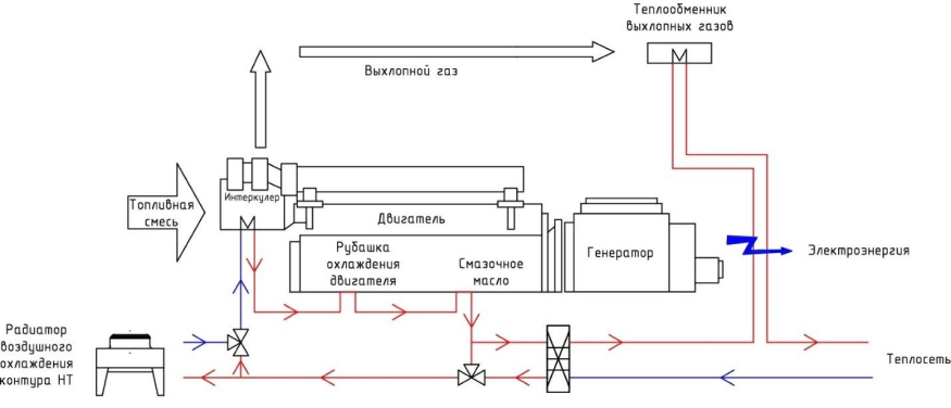
Figure 1. Scheme of operation of a gas piston plant
The gas is supplied through the pipeline to the gas control line, in which the pressure is regulated when the gas flow rate changes. Next, the gas enters the gas mixer, where it mixes with air in a certain proportion. Next, the gas-air mixture enters the turbine compressor and is fed into the cylinders. At the moment of compression, the gas-air mixture is ignited by the electric discharge of the candle and, expanding during combustion, pushes the piston. The piston’s energy is transferred to the crankshaft, which in turn rotates the alternator shaft through a flexible coupling.
After the combustion of the mixture, the exhaust gases enter the turbine and set it in motion, starting the compressor. Further, the exhaust gases are discharged through the muffler into the atmosphere.
The electricity generated by the generator is transmitted through the switchgear to the electrical consumers. There are two modes of operation of the generator “in parallel with the network” and “island” (autonomous).
In the “in parallel with the network” mode, the source of electricity is both the generator and the external power grid. When the GPU is started, the automation that controls the operation of the generator synchronizes the voltage in magnitude and phase with the mains voltage and, at the moment of their equality, closes the generator switch. With a lack of generator power, additional energy gets from the network, with an excess it is given to the network. Often, grid companies prohibit the flow of energy into their networks, then it is necessary to automatically limit the generated power of the generator in order to prevent power flow.
In offline mode, all electricity is consumed by the connected load. The generation power depends only on the connected load, but should not be less than the technological minimum of 50% and more than 100% of the rated power of the gas piston unit.
The engine has two cooling circuits: high temperature (HT) and low temperature (LT). The HT-circuit includes the “cooling jacket” of the engine, the oil cooling heat exchanger, the 1st stage of cooling the gas-air mixture. The heat from the coolant (coolant) of the HT circuit is recovered by means of a plate heat exchanger into the external heat network and goes to the consumers. In the absence of heat extraction to the external network, heat is dissipated into the atmosphere through an air-cooled radiator (“dry cooling tower”).
In the low-temperature (LT) circuit, the 2nd stage of cooling the gas-air mixture is turned on. The heat from this circuit is dissipated to the atmosphere through an air-cooled radiator (“dry cooler”).
The structure of the gas-piston plant container includes a ventilation system for supplying the engine with air and removing excess heat from the engine room.
Control of a gas piston power plant:
Indication of the current parameters of the gas piston unit from the built-in panel, signaling warnings, current errors, accidents
Storage, transmission of data on the operation of engines of a gas piston power plant for the past period of operation;
Regulation of the power, voltage and frequency of the generated electric current, electronic protection systems
Control of the operation of the engine of a gas piston power plant
Control of the operation of the gas engine cooling system
Management of the ventilation system of the machine room
Remote access to data on operation, diagnostics and control of a gas piston power plant
Feedback
Send your message and our manager will call you back as soon as possible